Recently I learned about a new, low cost, way of controlling movement in model train layouts. The servo motor. Since I have no experience with this little “can do anything” thingy, I went online to do some research. One of the things I quickly learned was that controlling the servo motor does not work with regular DC volt, but PWM, meaning pulse width modulation.
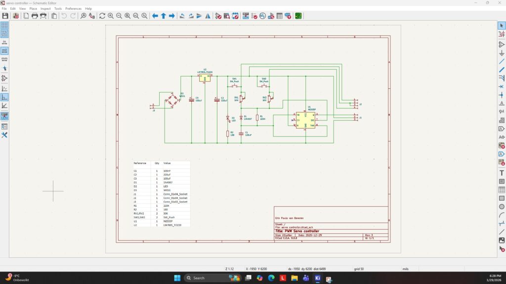
Servo motors can be controlled with Arduino and Raspberry pie micro controllers, but that is not cost effective if used for a simple movement. I like to control the servo motor the old fashion way with simple electronics. And no programming required.
This pulse width modulation is a method of representing a signal as a DC rectangular wave with a frequency of 20 ms (50Hz) with a varying duty cycle.
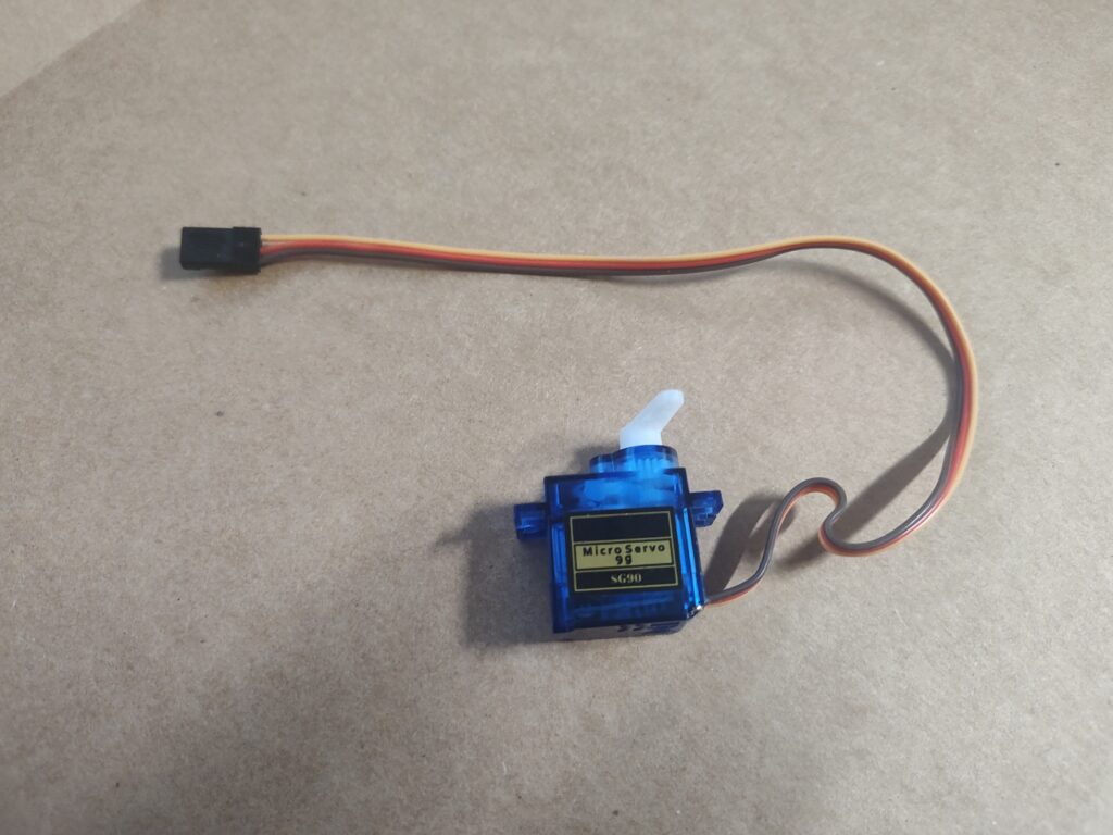
A servo motor can turn a maximum of 180 degrees, so it is not a continuous rotation motor. A 1ms duty cycle (pulse) rotates the servo motor to the max left, a 2ms duty cycle (pulse) will rotate the servo motor to the max right, while a 1.5 ms duty cycle (pulse) places the servo motor in the center position. For my project I am using the SG90 micro servo motor which is low cost and easily available online at various retailers. I get mine at Amazon.
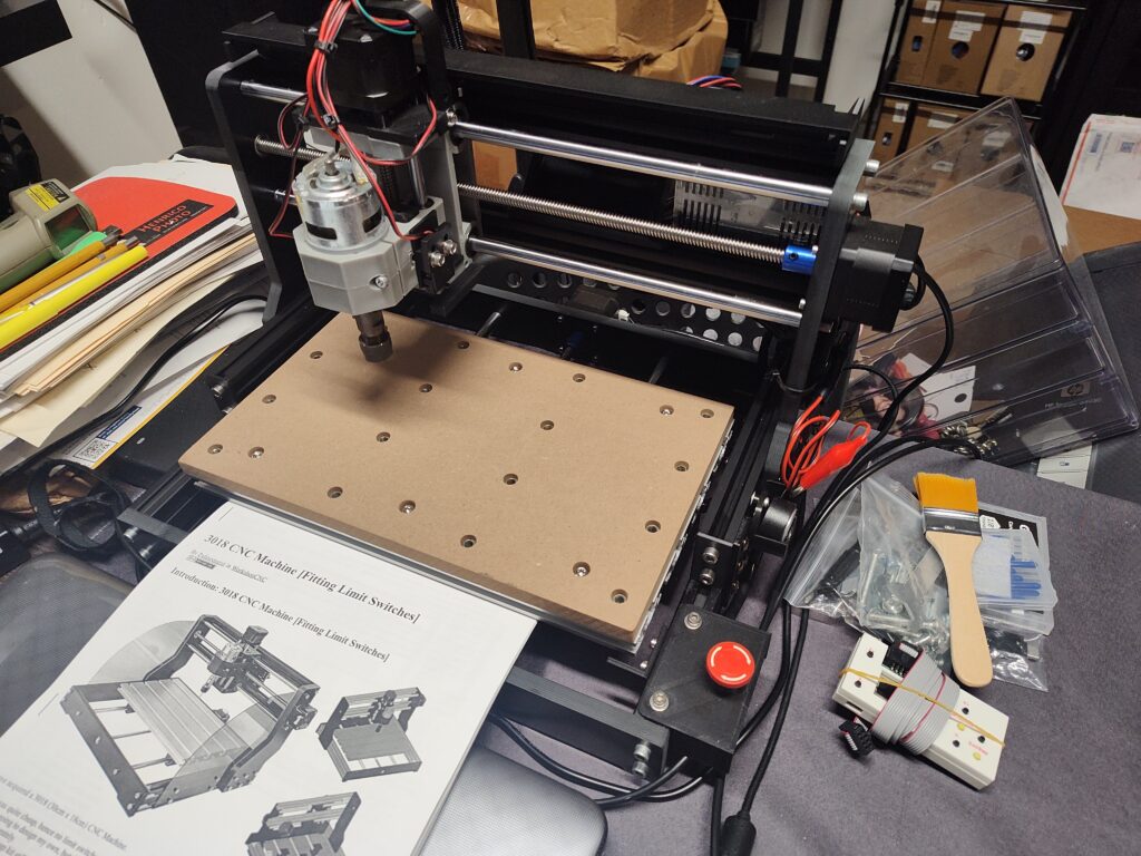
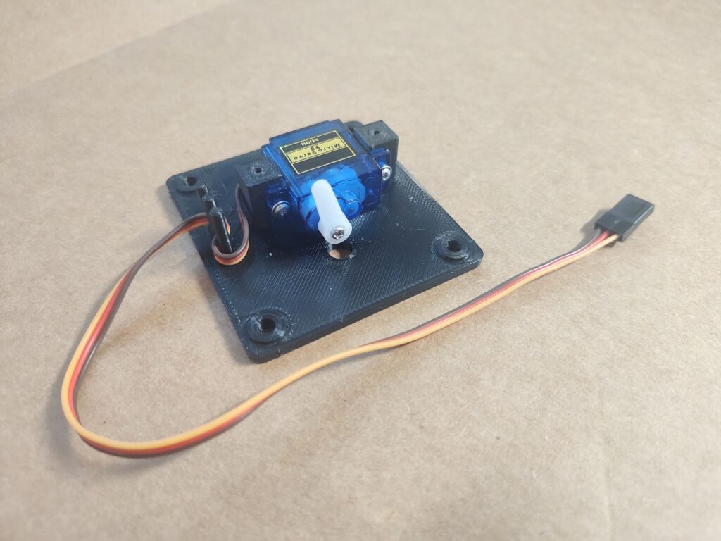
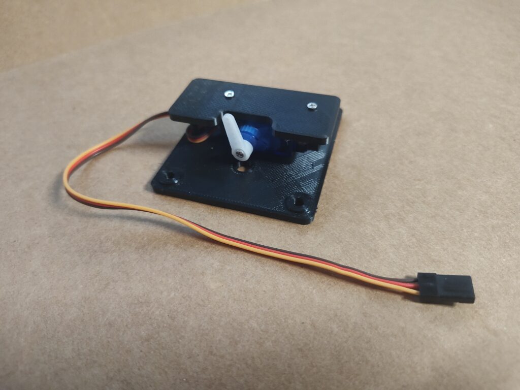
To make things move on the model train layout, the servo motor arm is attached to the model with a thin metal wire. The servo motor needs to be mounted out of sight underneath the subject requiring movement. This could be a turnout switch, a semaphore signal, a railroad crossing arm, a children’s playground, a small bridge and many more scenery items.
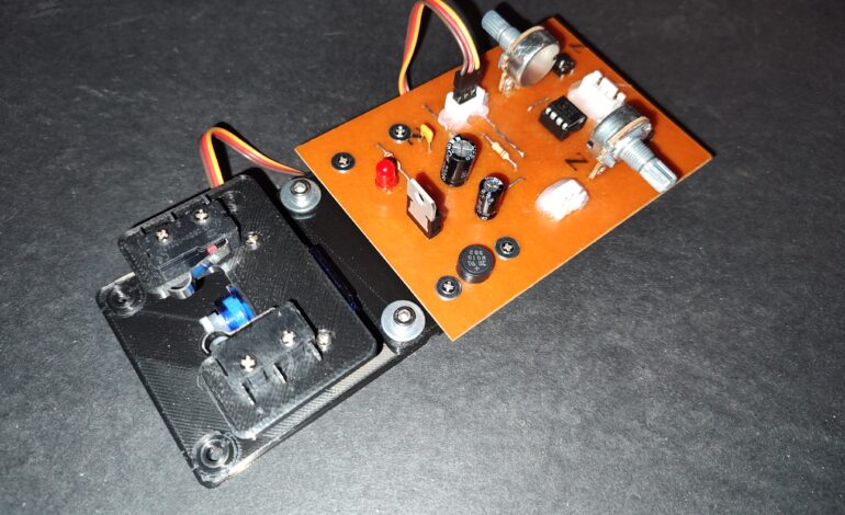
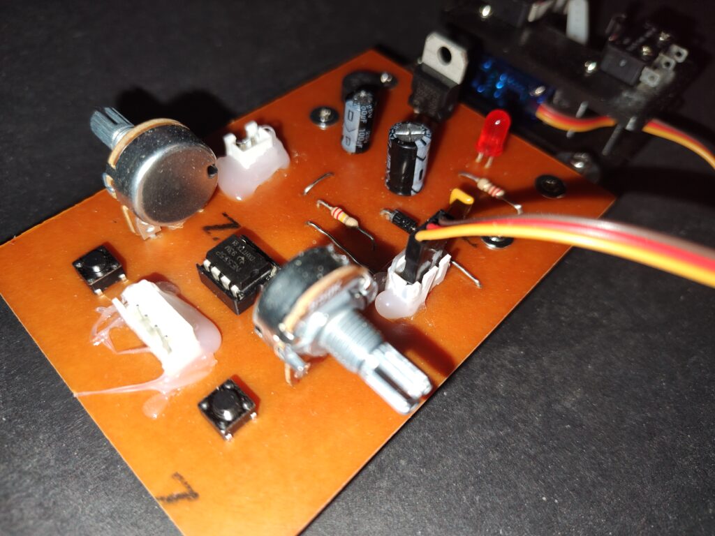
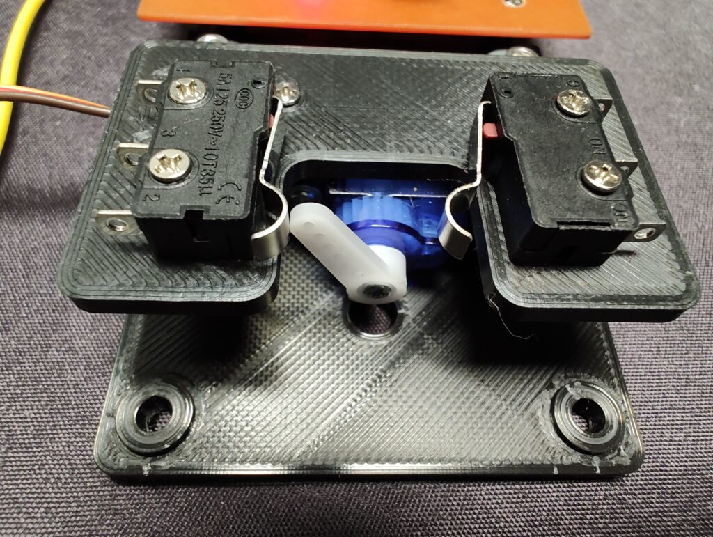
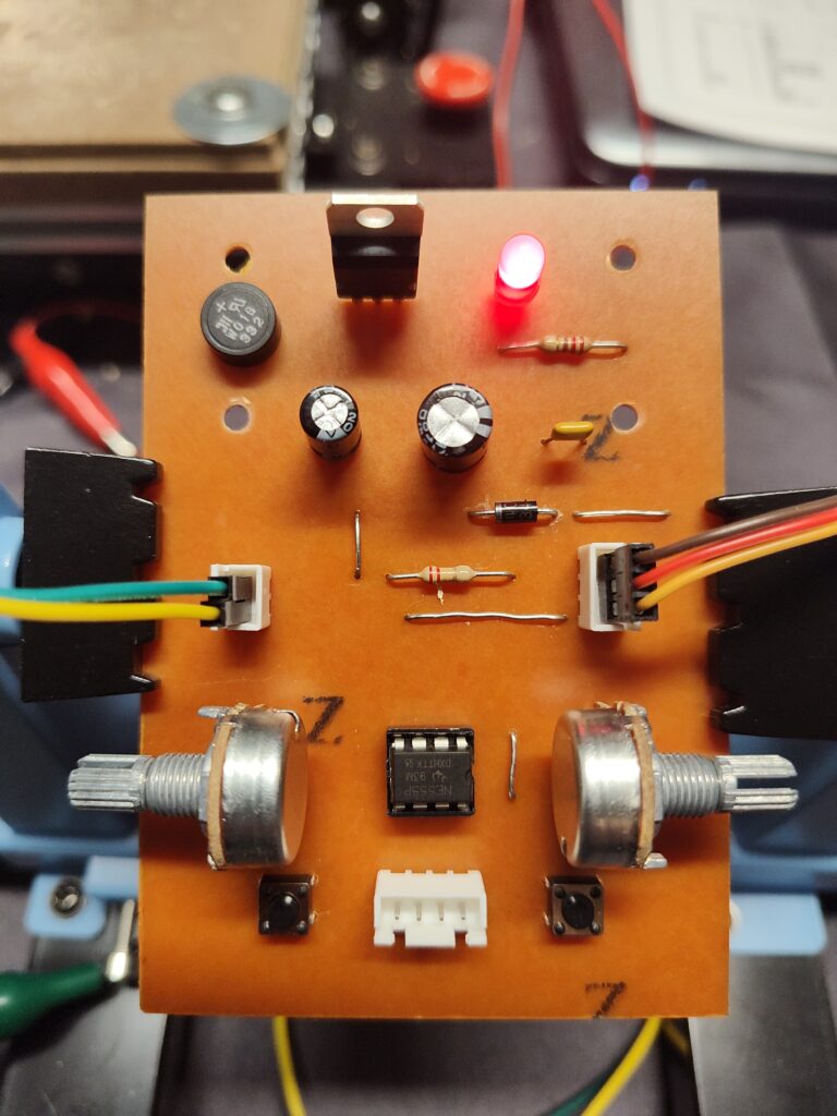
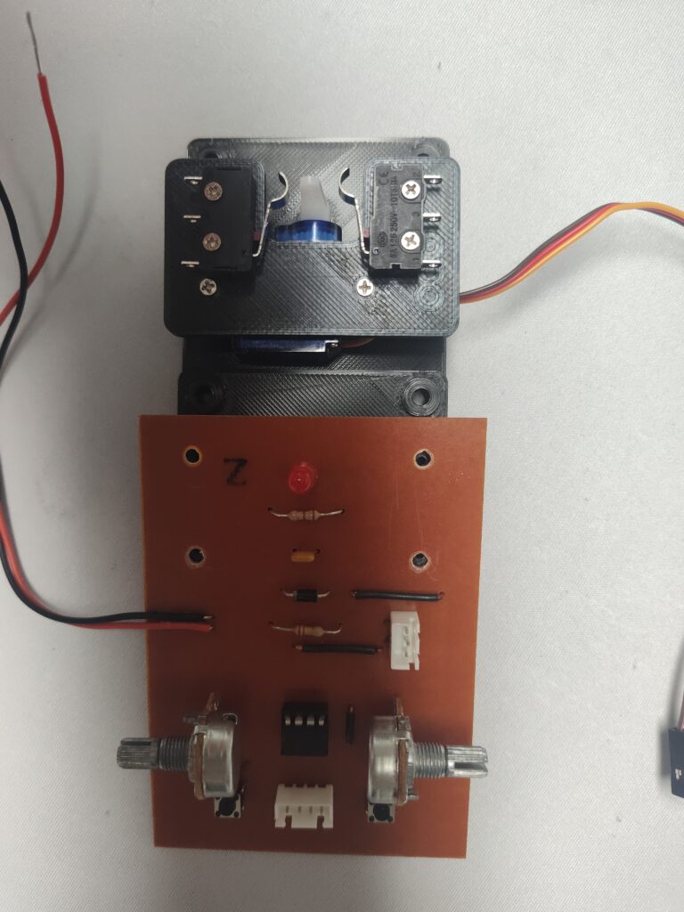
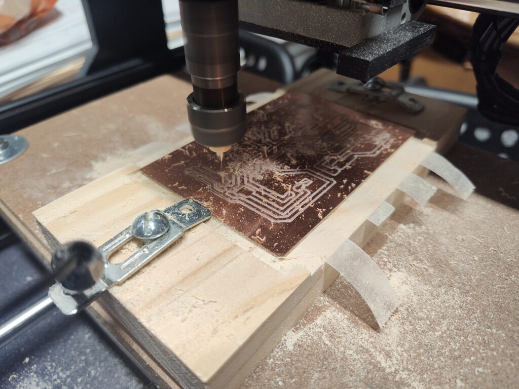
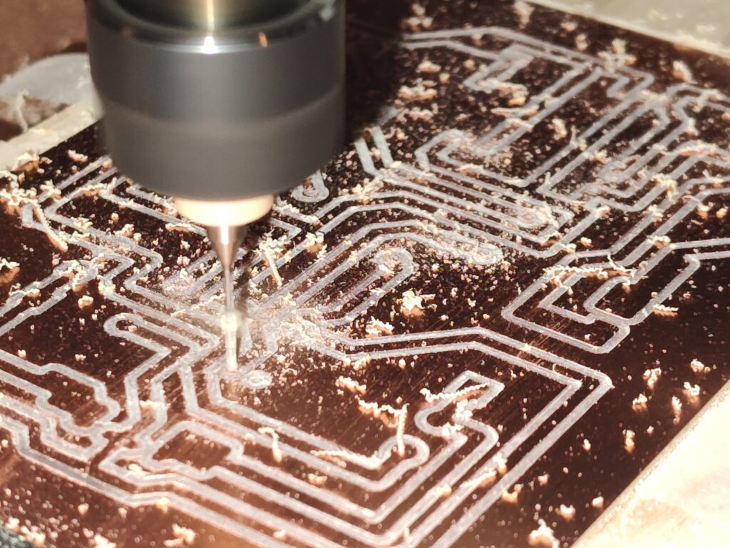
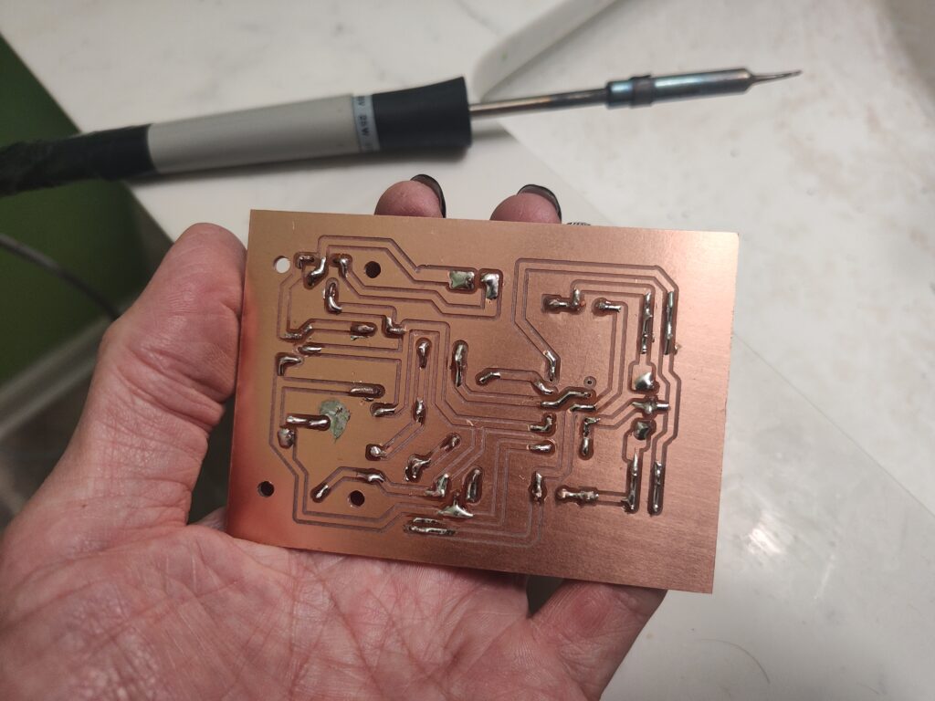
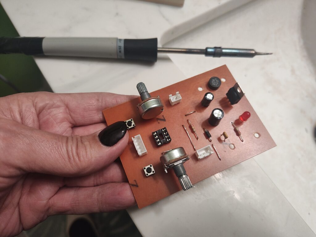
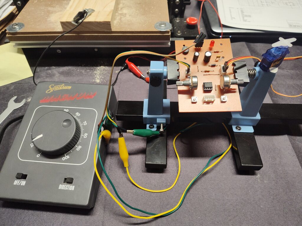
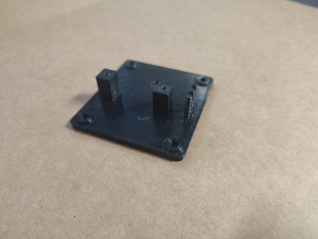
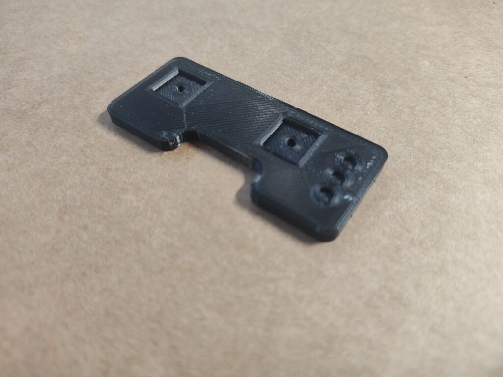
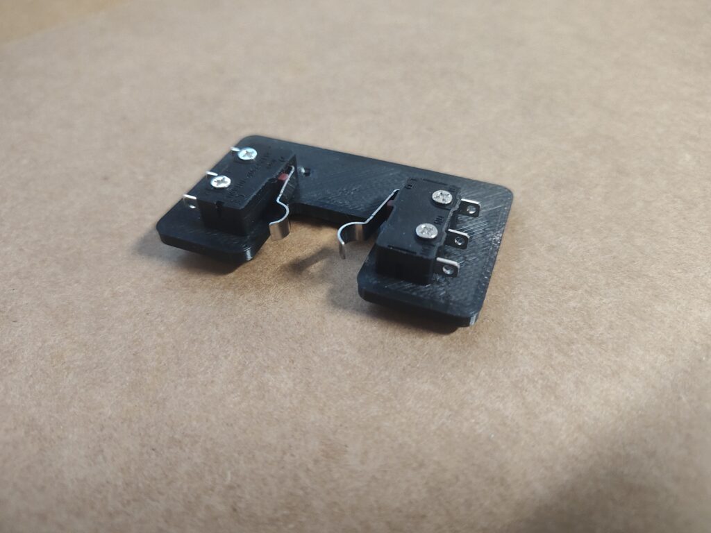
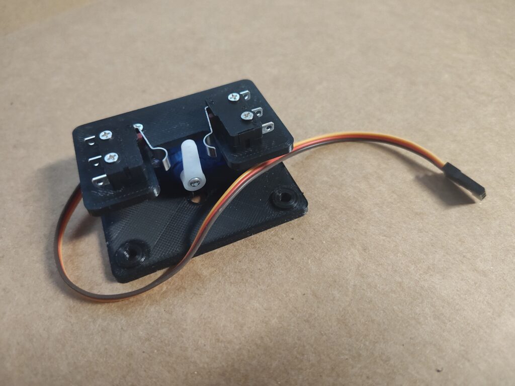
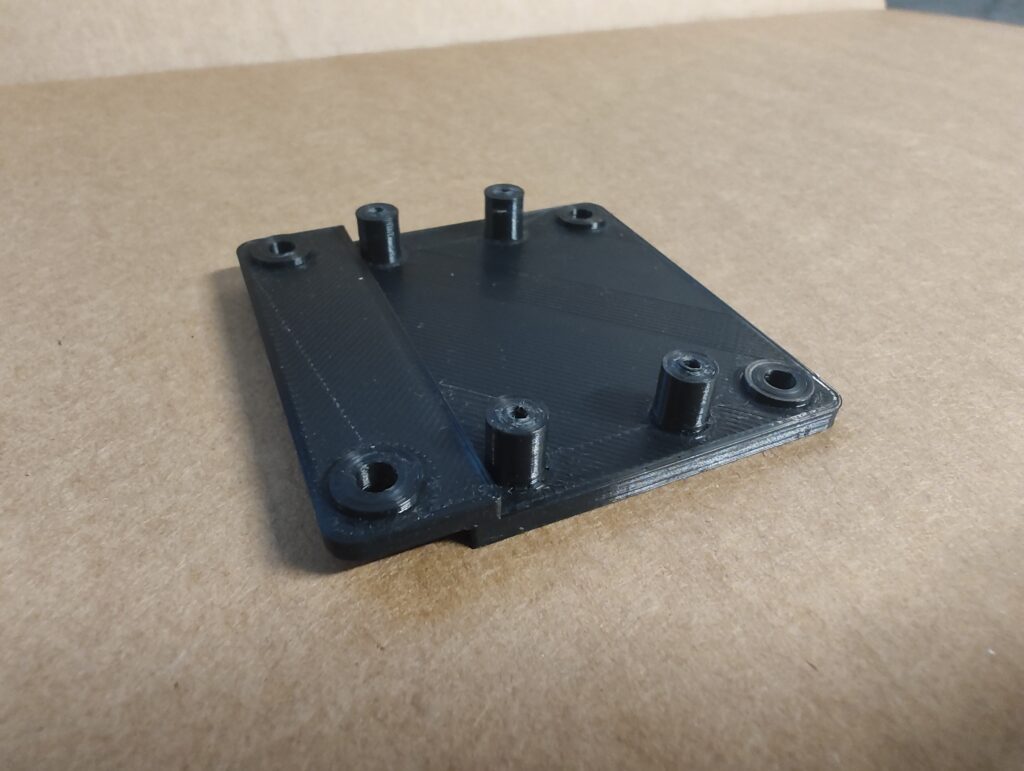
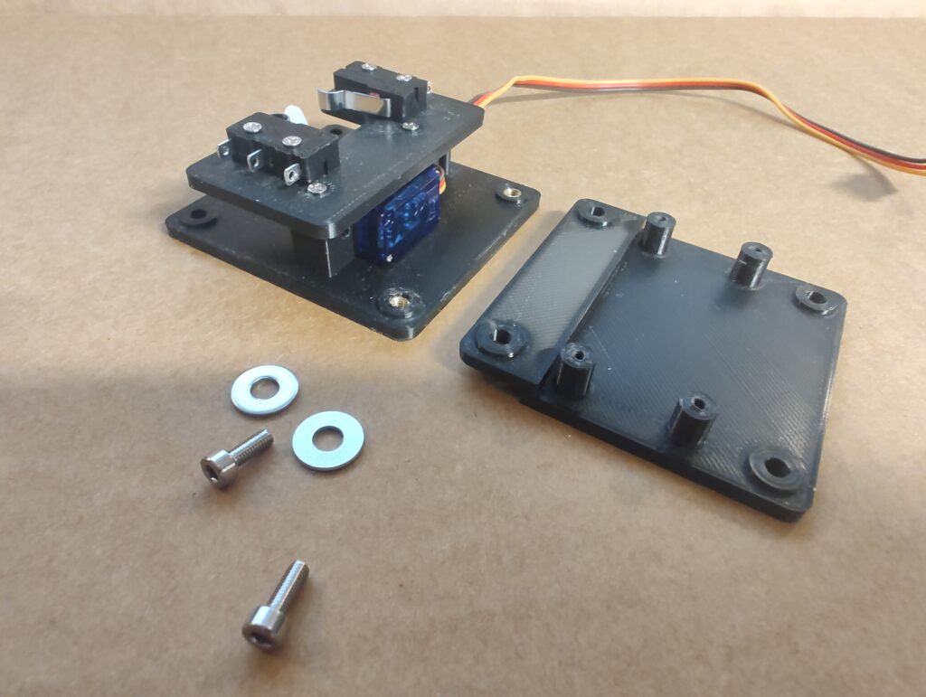
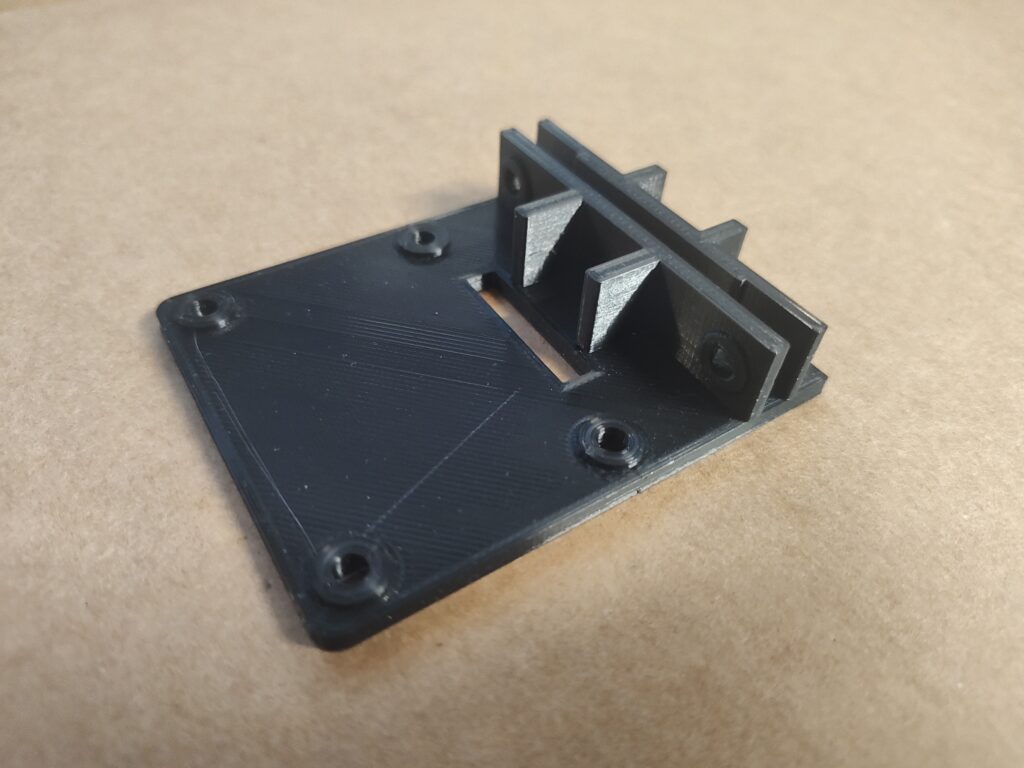
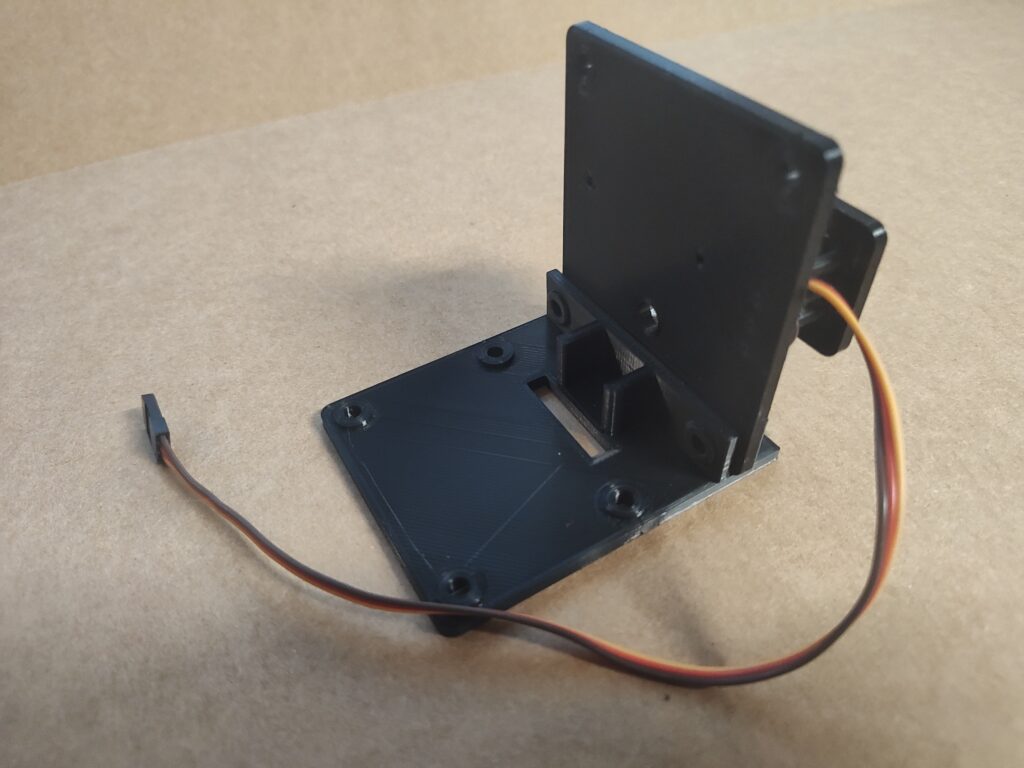
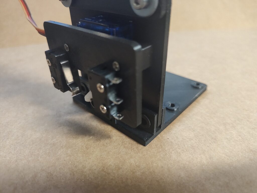
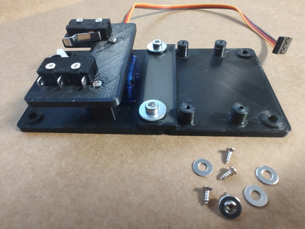
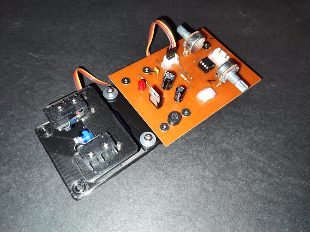
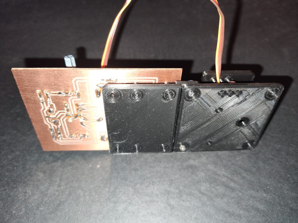
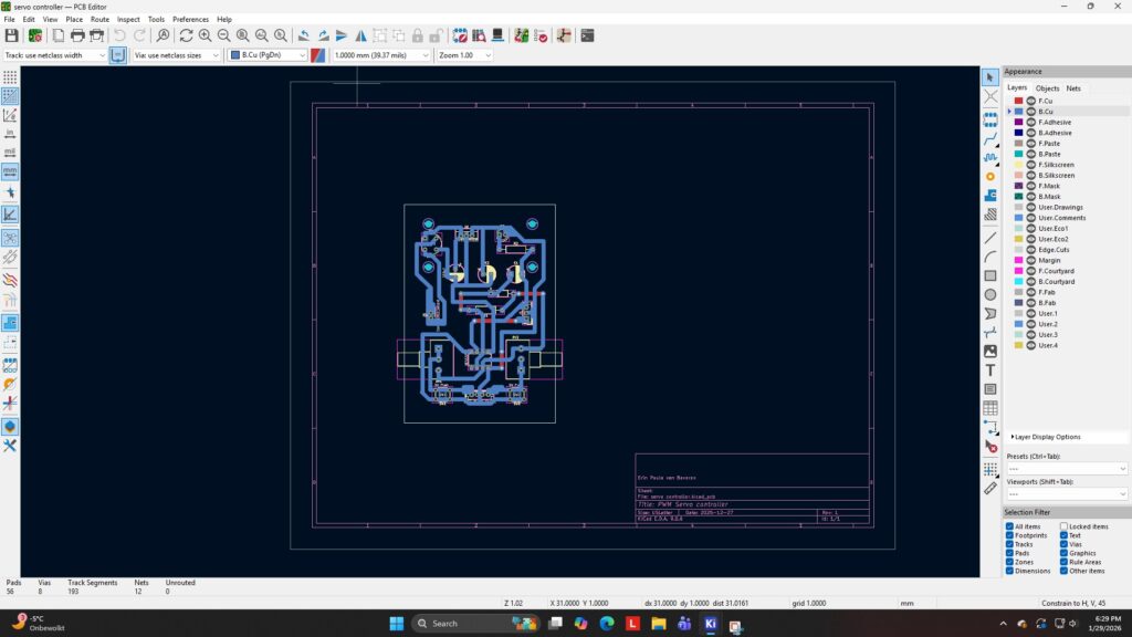
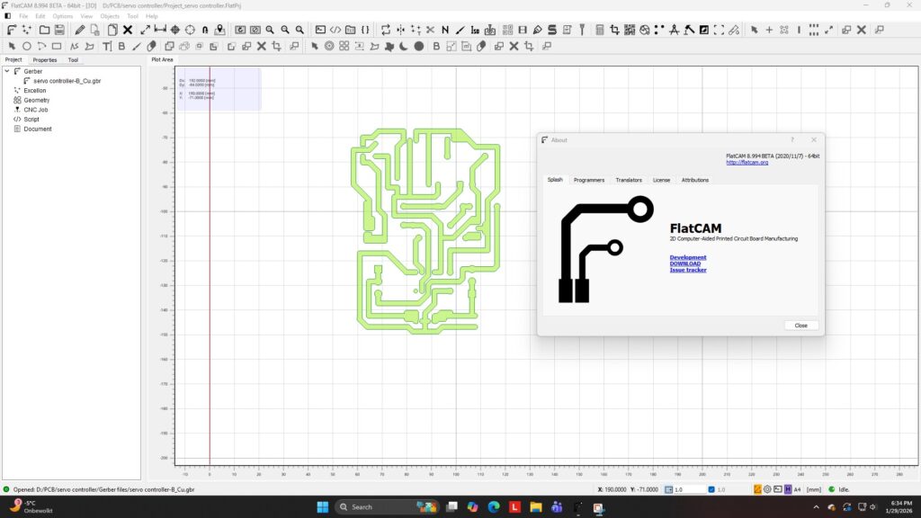
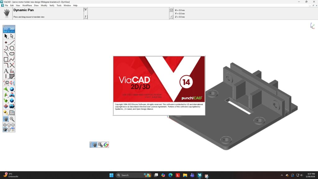
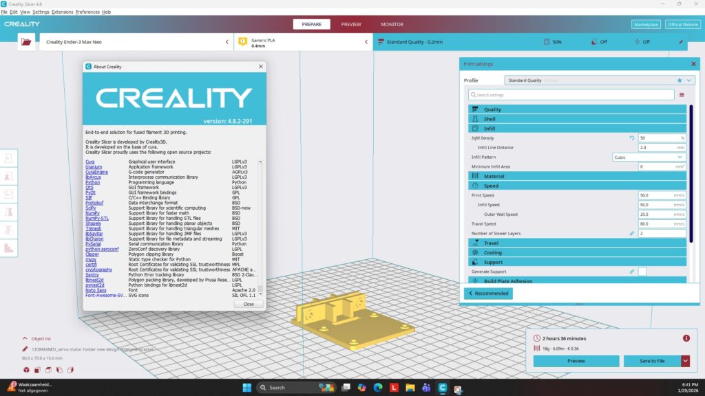
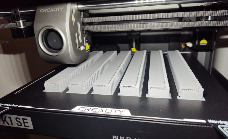
For this part I designed a few 3D printed mounts/brackets, that can be used in a modulair system. I also designed a bracket with micro switches, to have position feedback to be used for whichever function needed. This useful for signal lights or providing the correct power to a turnout switch center frog. My modulair system is just a simple way of adding a module that is needed. The PCB, printed circuit board, controlling the servo motor is attached to the bracket.
Useful links:
The servo motors on Amazon: SG90 servo motor on Amazon
The servo motors that I have: SG90 servo motor data sheet